← Home · Geophysics

Seismic Tomography (Refraction/Reflection) Surveys in Wigan

Together, we solve the challenges of tomorrow.

READ MORE →

The buried valleys and Pennine Coal Measures beneath Wigan create a subsurface riddled with velocity contrasts that conventional boreholes often miss. Drift deposits here can exceed 30 metres in places like Ince or Pemberton, masking abandoned mine workings and sandstone channels where seismic velocity shifts abruptly from under 800 m/s in soft alluvium to over 2,500 m/s in competent rock. Seismic tomography (refraction/reflection) maps these transitions continuously, providing the lateral coverage essential for foundation design near known fault lines such as the Wigan Coal Measures syncline. Where drilling alone leaves gaps, spt-drilling provides point-specific N-values that tomography velocity models then help extrapolate across the full site footprint.

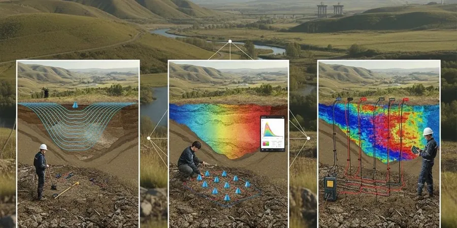
Velocity tomography resolves the rockhead profile beneath Wigan's drift cover where drilling alone would interpolate across tens of metres of uncertainty.

Process overview

The Pennine rainfall regime saturates the glacial till mantle across much of the borough, lowering seismic velocities in the weathered zone and demanding careful first-break picking to distinguish true refractors from moisture-softened surface layers. Our field crews deploy 24- to 48-channel arrays with accelerated weight drop or shotgun sources, generating P-wave and S-wave profiles that resolve strata down to 40–60 metres depth, sufficient to image the rockhead interface above the Middle Coal Measures. Processing follows BS 5930 guidelines, with tomographic inversion producing smoothly varying velocity grids rather than simple layered models. For sites where mining voids are suspected, the velocity tomography can be integrated with resistivity profiling to cross-validate cavity locations, since air-filled voids create both low-velocity and high-resistivity anomalies in the respective datasets.
Seismic Tomography (Refraction/Reflection) Surveys in Wigan
Technical reference image — Wigan

Local context

A common error on brownfield sites around Wigan is relying solely on SI boreholes spaced 20–30 metres apart, assuming the rockhead is planar between them. Glacial erosion of the Pennine Coal Measures has carved irregular channels into the bedrock, and a piled foundation terminating on a sandstone high can be flanked by soft infill just two metres away. Undetected, this differential stiffness produces unacceptable settlement gradients in the superstructure. Seismic tomography (refraction/reflection) eliminates that interpolation gamble by delivering a near-continuous rockhead profile, and the velocity data itself feeds directly into B-value calculations for dynamic modulus estimates, particularly important for structures subject to vibration from the West Coast Main Line or local industrial plant.

Need a geotechnical assessment?

Reply within 24h.

Email: contact@geotechnical-engineering.biz

Technical parameters


ParameterTypical value
Typical survey depth (refraction)30–60 m depending on spread length
Source typeAccelerated weight drop, 12-gauge shotgun, sledgehammer
Geophone array24–48 channel, 4.5 Hz vertical or 14 Hz horizontal
Velocity resolution (P-wave)Typically ±50 m/s in tomographic grid
P-wave velocity range (glacial till)400–1,800 m/s depending on saturation
P-wave velocity range (sandstone/rockhead)2,200–4,500 m/s
Data format deliverablesSEG-2, SEG-Y, depth-section DXF, PDF report
Applicable standardBS 5930:2015 + Eurocode 7 (BS EN 1997)

Additional services

01

P-Wave Refraction Tomography

Primary method for mapping rockhead and assessing rippability across glacial till and Coal Measures sequences. Provides continuous velocity cross-sections used to derive small-strain stiffness for settlement analysis.

02

S-Wave (MASW/ReMi) Profiling

Generates shear-wave velocity profiles for site classification to BS EN 1998 and seismic hazard assessment. Essential where Vs30 zoning is required for structural design in former mining areas.

03

Cross-Hole & Downhole Seismic

High-resolution interval velocity measurement between boreholes or within a single borehole, calibrated against SPT N-values for precise dynamic modulus determination at depth.

Reference standards

BS 5930:2015 (Code of practice for ground investigations), Eurocode 7 Part 1 & 2 (BS EN 1997-1:2004, BS EN 1997-2:2007), ASTM D5777-18 (Standard Guide for Using Seismic Refraction), BS 5607:2017 (Safe use of explosives in construction — where applicable)

Quick answers

What depth can seismic refraction reach in the Wigan area?

With a 115-metre spread length and a weight-drop source, we typically image the refractor at 30 to 40 metres depth through the glacial till. In favourable conditions, reflection processing on the same dataset can extend usable coverage to 60 metres or more, sufficient to reach the sandstone bedrock across most of the borough.

How much does a seismic tomography survey cost for a typical Wigan site?

A single-line refraction profile with 24 geophones and tomographic processing falls between £2,410 and £3,990, depending on spread length, source type, and terrain access. Multi-line or 3D grid surveys are priced per linear metre after an initial review of the site plan and mining records.

Can seismic methods detect old mine workings beneath the site?

Seismic velocity alone cannot directly image small voids, but the tomographic grid often reveals velocity anomalies consistent with collapsed workings or fractured roof rock. The most reliable approach combines seismic tomography for rockhead mapping with electrical resistivity profiling to cross-validate air-filled or water-filled cavity signatures.

Location and service area

We serve projects across Wigan and its metropolitan area.

View larger map